
Managing product launch cycles requires precise transparency over supply chain timelines and engineering constraints. When sourcing commercial hardware enclosures, understanding how long custom EVA tooling development takes is essential for seamless market synchronization. However, speed must be paired with accurate engineering; ignoring critical material dynamics like the natural EVA shrinkage rate or tight zipper radius design parameters can result in compromised protection or failed quality inspections.
Critical Milestones in Custom EVA Tooling Development
-
Days 1–3: CAD file validation and CNC G-code programming.
-
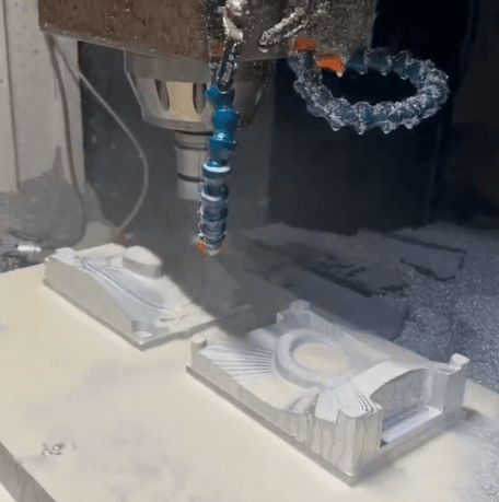
Days 4–7: Precision CNC milling of sample molds.
-
Days 8–10: Trial pressing and delivery of first-article samples.
-
Days 11–25: Mass production tooling fabrication and automated optimization.
Timeline Breakdown: How Long Does Custom EVA Tooling Development Take?
For supply chain managers, scheduling custom EVA tooling development requires mapping out two distinct phases: prototyping tools and mass production tools.
The initial step involves fabricating a single-cavity sample mold dedicated to producing the first physical prototypes for mechanical evaluation. The typical tooling lead time for this phase spans 7 to 10 working days. This timeframe covers importing the final 3D files, computing the CNC tool paths, executing the physical metal milling, and performing a trial pressing to check material behavior under thermal stress.
Once the physical prototype passes internal validation tests, the project advances to production tooling development. These production molds are typically multi-cavity tools machined from premium aluminum alloys designed to withstand thousands of high-tonnage compression cycles. Manufacturing these robust tool sets requires 15 to 20 days. Factors that can extend this period include intricate exterior textures, complex engraved corporate logos, or multi-tiered layouts that require secondary slide-actions within the press machinery.
5 Common Design Mistakes in Custom EVA Case Projects
Avoiding critical engineering errors during the initial layout phase protects your development budget and prevents costly production delays. Below are the five most frequent oversights discovered during technical product audits.
Mistake 1: Disregarding the Natural EVA Shrinkage Rate
Ethylene-vinyl acetate is an expanded copolymer. When it is compressed under temperatures exceeding 150°C and subsequently cooled, it undergoes volumetric contraction. The standard EVA shrinkage rate typically fluctuates between 0.5% and 1.5% depending heavily on the foam density, durometer hardness, and selected fabric laminates. If an industrial designer bases their calculations on a 0% shrinkage matrix, the finished case will scale down smaller than intended, preventing your devices from fitting inside its designated slot.
Mistake 2: Sharp Zipper Radius Design
A frequent structural flaw is specifying sharp 90-degree corners on rectangular cases to achieve a modern, geometric aesthetic. However, industrial zippers cannot track smoothly through sharp corners. If the corner bending radius (R-angle) drops below the physical limit of 25mm, the zipper teeth experience excessive friction, leading to premature track failure, jamming, and cloth tearing during standard operation.
Mistake 3: Inadequate Draft Angles on Deep Enclosures
For deep-dish travel cases, the vertical walls cannot be perfectly perpendicular. Designers must integrate a clear draft angle—ideally maintained between 3 to 5 degrees. Without this intentional slope, the vacuum forces and friction generated during compression molding make it nearly impossible to cleanly extract the cooled shell from the mold cavity, resulting in stretched fabric or deformed corners.
Mistake 4: Overlooking Cable and Accessory Spatial Allowances
Product teams often focus entirely on the main device housing while failing to reserve space for essential peripherals. Power adapters, charging cradles, calibration cables, and region-specific manuals require independent layout accommodations. Failing to design an integrated top-lid mesh pocket or secondary under-foam storage channel forces users to cram accessories directly against screen faces, risking severe component damage.
Mistake 5: Incorrect Foam Density Selection
Choosing foam based purely on soft tactile feedback rather than structural energy dissipation often yields poor protection. Low-density polyurethane foams bottom out under moderate impacts, offering minimal insulation for heavy instruments. Conversely, overly rigid high-durometer foams can scratch delicate surface coatings.
Failure Mode and Effects Analysis (FMEA) for EVA Cases
Review this quality engineering reference chart to recognize and mitigate potential structural risks before initializing full-scale tooling investment.
| Engineering Failure Mode | Root Cause Analysis | Corrective Design Action |
| Zipper binding or jamming | Corner radius drops below the 25mm threshold. | Increase corner curvature to ensure fluid zipper travel. |
| Fabric delamination/peeling | Insufficient heating or improper adhesive volume. | Optimize infrared oven temperature profiles and press dwell time. |
| Internal component rattling | Incorrect shrinkage allowance calculation. | Readjust CAD files to match the exact shrinkage factor of the foam. |
| Shell warping / twisting | Asymmetrical wall cooling or uneven press pressure. | Recalibrate internal mold cooling lines and verify plate leveling. |
Maximizing Tooling ROI and Mitigating Risk
To secure your production investment, implement clear quality validation protocols before approving the mass production tooling kickoff.
Risk Mitigation Case Study: When engineering a rugged handheld terminal case for a US client, developers utilized a low-cost epoxy resin sample mold to produce three functional prototypes before cutting the main production tools. The trial revealed that the high-weave fabric caused micro-stress deformations along the corners under high pressure. By adjusting the corner chamfer coordinates on the final production aluminum molds ahead of time, the client avoided thousands of dollars in direct mold modification and re-tooling costs.
Always insist on a formal First Article Inspection (FAI) report generated from the initial single-cavity sample tool. This sample should undergo real-world drop testing to verify that the energy absorption properties of the custom EVA foam inserts match your specifications. Only after the physical prototype successfully passes these drop tests and environmental aging simulations should you authorize the final engineering release for the production aluminum tooling.
According to the American Society for Testing and Materials (ASTM D4169 performance testing for shipping containers), any commercial packaging solution must undergo continuous vibration and random drop validation. By precisely controlling the tolerance distribution throughout tool development, our engineering processes ensure the finished hard cases pass complete simulated distribution and logistics transit tests.
All precision aluminum molds are manufactured in-house via high-speed CNC machining centers, guaranteeing complete supply chain control and data security. If you are ready to kick off a new hardware enclosure project, submit your design drawings or deployment timelines to our technical team for an optimized mold quote and timeline schedule.
Custom EVA Tooling Development FAQs
What happens if a design mistake is found after the production aluminum mold is completed?
Because aluminum molds are subtractive CNC-machined tools, minor modifications—such as widening a pocket or deepening a channel—can sometimes be corrected by secondary precision milling. However, if the external dimensions need to be increased or the zipper line changed, a completely new mold must be fabricated.
Can the tooling lead time be accelerated for urgent project launches?
Yes, the tooling lead time can be optimized by running 24/7 continuous operations on high-speed CNC milling centers. Providing flawless STEP files that strictly follow standard draft angles and shrinkage parameters also eliminates engineering review loops, saving several days.
How many product units can be manufactured from a single production mold?
High-grade 6061 aluminum production molds are designed for long-term industrial use, maintaining perfect dimensional stability for 50,000 to 100,000 compression cycles before requiring replacement or re-cutting.
How do you protect our intellectual property during the tooling phase?
All client files, 3D models, and custom mold designs are managed through an encrypted, isolated Product Lifecycle Management (PLM) system. Access is strictly limited to the assigned project engineers and CNC machinists, ensuring your proprietary product designs remain confidential prior to your market launch.